| SUNGAI SELANGOR WATER SUPPLY SCHEME PHASE - 1 |
| Purpose of Project | | Water Supply Project to
Kuala Lumpur and Selangor | 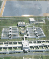 |
| Term of Work | | 1990 - 1993 | |
| Design Output | | 950 Mld (Million liter per day) | |
| Client | | Jabatan Bekalan Air Selangor
(Selangor Water Department in Malaysia:JBA) | |
| Consultant Engineer | | SMHB Sdn. Bhd. (Malaysia) | |
| Contract Amount | | RM 830 Million | |
| Location | | Selangor and Kuala Lumpur in Malaysia. | |
|
work summary
a.Headworks(Intake and treatment works)
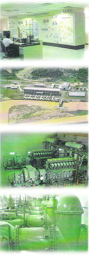
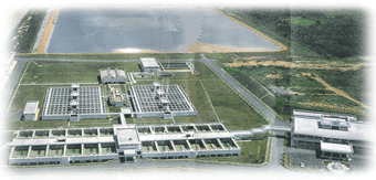
The Headworks comprise intake works and treatment works with plant installation to produce a nominal output of 950 Mld of treated water.
The intake works consist of electrically operated river gates, intake plant with sand hoppers complete with ejector system and bandscreens,
raw water pumping station with six units of raw water pumps and with provision for extension of another four pumps in the future,
a stand-by generating plant, 33Kv switch house complete with electrical power distribution system and a main control building.
The treatment works consist of an aerator, six settling tanks, 24 units filter tanks, a sludge disposal plant,
a chemical plant, a contact and clear water tank,
a treated water pumping station with six units treated water pumps and with provision for extension of seven pumps in the future, a stand-by generating plant,
a 33 kV switch house and electrical power distribution system and an administration building.
To ensure efficient management and operation of the works, the plants are incorporated with automated design.
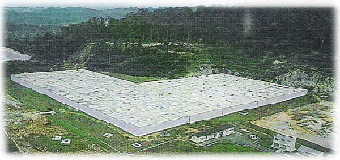
b. Storage And Distribution Supply works
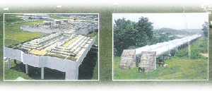
The storage and distribution supply works comprise approximately 103 km of steel trunk mains ranging from 1150mm-2100mm diameters;
and seven twin compartment reinforced concrete terminal reservoirs of capacities ranging from 18Ml (4kg)-186Ml (41kg) storage.
The treated water from the headworks is transferred by treated water pumps to a balancing reservoir of capacity 186 Mld at Matang Pagar
through twin 2100mm diameter cement lined steel pipes. From Matang Pagar Reservoir,
water gravitates through a 2050mm diameter cement lined steel pipeline with 1850 mm diameter branch to a distribution
reservoir of capacity 23 Ml at Bukit Jelutong is 1850mm diameter mm and 1150mm diameter respectively.
A second pipe of 1850mm diameter carries water by gravity from Matang Pagar to Kepong Estate Reservoir, having capacity of 43 Ml.
From Kepong Estate Reservoirll water gravitates through a 1550mm diameter cement lined steel pipe to a distribution reservoir
at Batu Estate with capacity 27 Ml . Additionally, water is pumped from Kepong Estate Reservoir to Dusun Kubong distribution
reservoir of capacity 18 Ml through a 1200mm diameter cement lined pipe.
At Batu Estate Reservoir, the water gravitates through a 1200mm diameter cement lined pipe to a distribution reservoir at Sentul Hill of capacity 27Ml.
|
 |
|
  |
| Click to enlarge |
|
| KENERING DAM HYDRO-ELECTRIC PROJECT |
| Purpose of Project | | Hydro Power Generation | 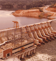 |
| Term of Work | | 19July1980 - 1October1983 (39Months) | |
| Design Output | | 120,000KW (40,000x3Nos) | |
| Client | | National Electricity Board of Malaysia (NEB) | |
| Consultant Engineer | | Shawinigan Engineering Company (Canada) | |
| Contract Amount | | RM 110 Million (11,362Milion yen) | |
| Location | | Perak, in Malaysia. | |
|
|
|
|
|
| Type | | Combined Dam of Rcckfill and Concrete Gravity Type |
| Dam Height | | 44.2m |
| Dam Crest Length | | 561m (Concrete:263m+Rockfull:298m) |
| Dam Volume | | 737,000m3 (Concrete:281,000m3+Rockfill:456,000m3) |
|
|
|
| Type | | Immediately beneath Dam and Semi subterranean Type |
| Buildings | | Wide 24m x Length 80m |
| Hydraulic Pipeline | | Internal Diameter〔ID〕:5.5m x 3Nos |
| Power Generator Unit | | Rated Power Output:
40,000Kw/No x 3Nos=120,000Kw Frances Turbine Type
|
|
|
|
| Catchments Area | | 240Km2 |
| High Water level | | EL 111.25m |
| Low Water level | | EL 108.20m |
| Reservoir Capacity | | 300Milion m3 |
|
|
|
|
|
ASAHAN HYDROELECTRIC PROJECT OF
TANGGA INTAKE DAM AND POWER STATION
|
| Purpose of Project | | Hydro Power Generation | 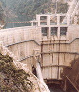 |
| Term of Work | | March 1979 - December 1983 | |
| Design Output | | 317,000KW (79,200x 4Nos) | |
| Client | | P.T. Indonesia Asahan Aluminum
Asahan Development Authority | |
| Consultant Engineer | | Nippon Koei Co., LTD (Japan) | |
| Location | | Sumatra in Indonesia | |
|
|
-Intake Dam- |
| Construction of the intake dam inclusive of spillway, stilling basin, and river diversion. |
|
| Type | | Concrete Arch Type |
| Dam Height | | 82.0m |
| Dam Crest Length | | 122m |
| Dam Concrete Volume | | 55,000m3 |
|
|
|
Construction of waterway structures inclusive of intake,
headrace tunnel, surge tank, penstock and tailrace.
|
|
|
|
|
|
|
| Type | | Circular Concrete Lined Pressure Tunnel |
| Diameter | | 6.1m |
| Length | | 1,615.7m |
|
|
|
| Type | | Restricted Orifice Type with Upper and Lower Chambers |
| Tank Diameter | | 9m |
| Tank Height | | 70.75m |
|
|
|
| Catchments Area | | 240Km3 |
| Type | | Steel Pipes with Concrete Lining |
| Length | | No.1 481m, No.2 465m |
|
|
|
| Type | | Overground, Indoor Type |
| Buildings | | Wide 29.6m x Length 94.8m x High 37.3m |
| Power Generator Unit | | Rated Power Output:79,200Kw/No x 4Nos=317,000Kw |
|
|
|
| Average Discharge Available | | 118.0m3/sec |
| Intake High Water level | | EL 506.0m |
| Intake Low Water level | | EL 502.0m |
| Effective Reservoir Capacity | | 710,000m3 |
| Average Gross Head | | 237.4m |
|
|
|
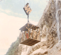 | 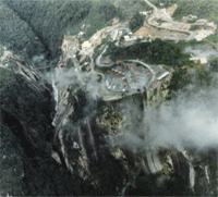 | | View From Up-Stream | View From Down-Stream
with TANGGA FALLS |
|
| Click to enlarge |
|
| TEMENGOR DAM HYDRO-ELECTRIC PROJECT |
| Purpose of Project | | Hydro Power Generation | 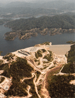 |
| Term of Work | | Dec1973 - Sep1977 (46Months) | |
| Design Output | | 380,000KW (95,000 x 4Nos) | |
| Client | | National Electricity Board of Malaysia (NEB) | |
| Consultant Engineer | | Shawinigan Engineering Co.,LTD (Canada) | |
| Contract Amount | | RM 160 Million (18,477Milion yen) | |
| Location | | Grik, Perak, in Malaysia. | |
|
|
|
|
|
| Type | | Center Core Rcckfill Type |
| Dam Height | | 126.5m |
| Dam Crest Length | | 498m |
| Dam Volume | | 6,983,300m3 |
|
|
|
| Type | | Center Core Rcckfill Type |
| Dam Height | | 30.0m |
| Dam Crest Length | | 107.0m |
| Dam Volume | | 757,000m3 |
|
|
|
| Type | | Overground, Indoor Type |
| Hydraulic Pipeline | | Internal Diameter〔ID〕:5.8m x 4Nos (Total Length=1,773m) |
| Power Generator Unit | | Rated Power Output:
95,000Kw/No x 4Nos=380,000Kw Frances Turbine Type |
|
|
|
| Catchments Area | | 3,400Km2 |
| Impounding Area | | 150Km2 |
| Reservoir Capacity | | 5,700Milion m3 |
|
|
|
|
|
TUNNEL EXCAVATION FOR KAMIOKA
MINERAL ORE INVESTIGATION PROJECT |
| Purpose of Project | | Mineral Ore Investigation (Zinc, Lead, Silver, Sulfuric acid) |
| Term of Work | | Mar 1970 - Aug 1975 |
| Client | | MITSUI MINING and SMELTING CO.,LTD |
| Contract Amount | | 1,500 Million yen |
| Location | | Kamioka, Gifu Pref., in Japan. |
|
|
|
| IMPROVEMENT WORKS FOR RIVER DISASTER |
| Purpose of Project | | Improvement Works for River |
| Term of Work | | May 1969 - Feb 1970 |
| Client | | River Department, Aichi Pref. |
| Contract Amount | | 194 Million yen |
| Location | | Kurokawa, Kitashitara, Aichi Pref., in Japan. |
|
| MISAKUBO DAM HYDRO ELECTRIC PROJECT |
| Purpose of Project | | Hydro Power Generation |
| Term of Work | | April 1967 - April 1969 |
| Client | | Electric Power Development Co.,Ltd. |
| Contract Amount | | 3,618 Million yen |
| Location | | Misakubo, Iwata, Shizuoka Pref., in Japan. |
|
|
| KOJIMA CORPORATION SDN.BHD. Copyright c 2019. All Rights Reserved. |
|
|